
 EN
EN
 ar
ar bg
bg hr
hr cs
cs da
da nl
nl fi
fi fr
fr de
de el
el hi
hi it
it ko
ko no
no pl
pl pt
pt ro
ro ru
ru es
es sv
sv tl
tl iw
iw id
id lv
lv lt
lt sr
sr sk
sk sl
sl uk
uk vi
vi et
et hu
hu th
th tr
tr fa
fa ms
ms hy
hy ka
ka ur
ur bn
bn mn
mn ta
ta kk
kk uz
uz ku
ku
Differential Water Level Gauge
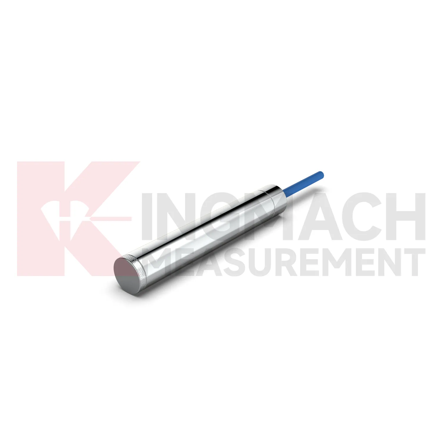
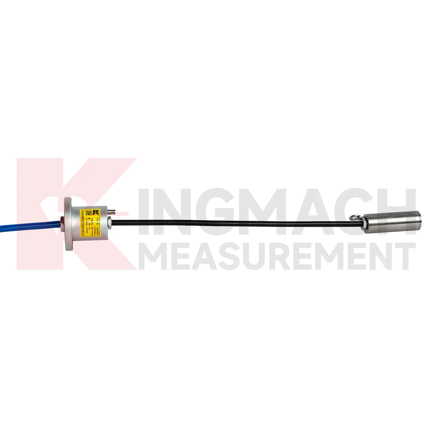
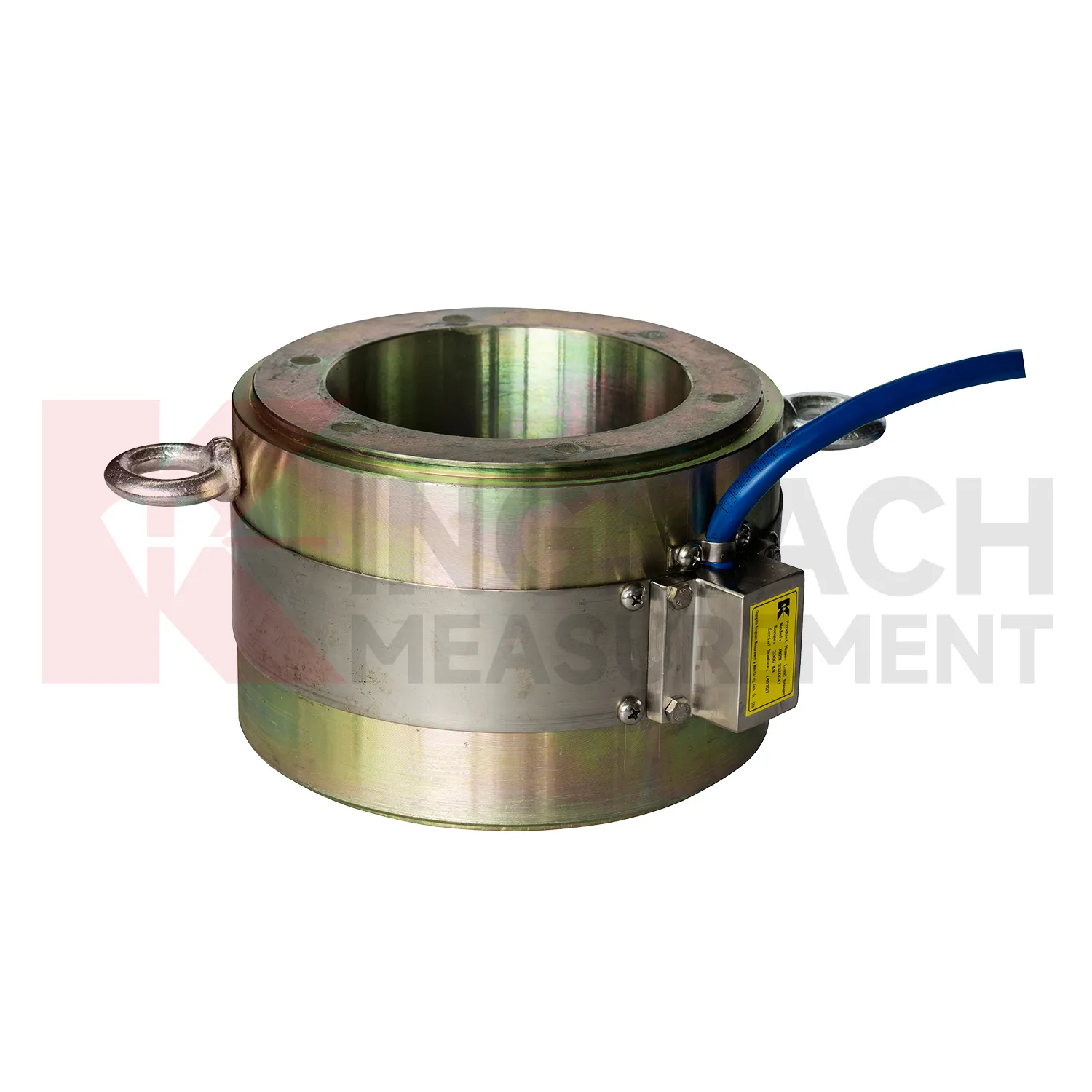
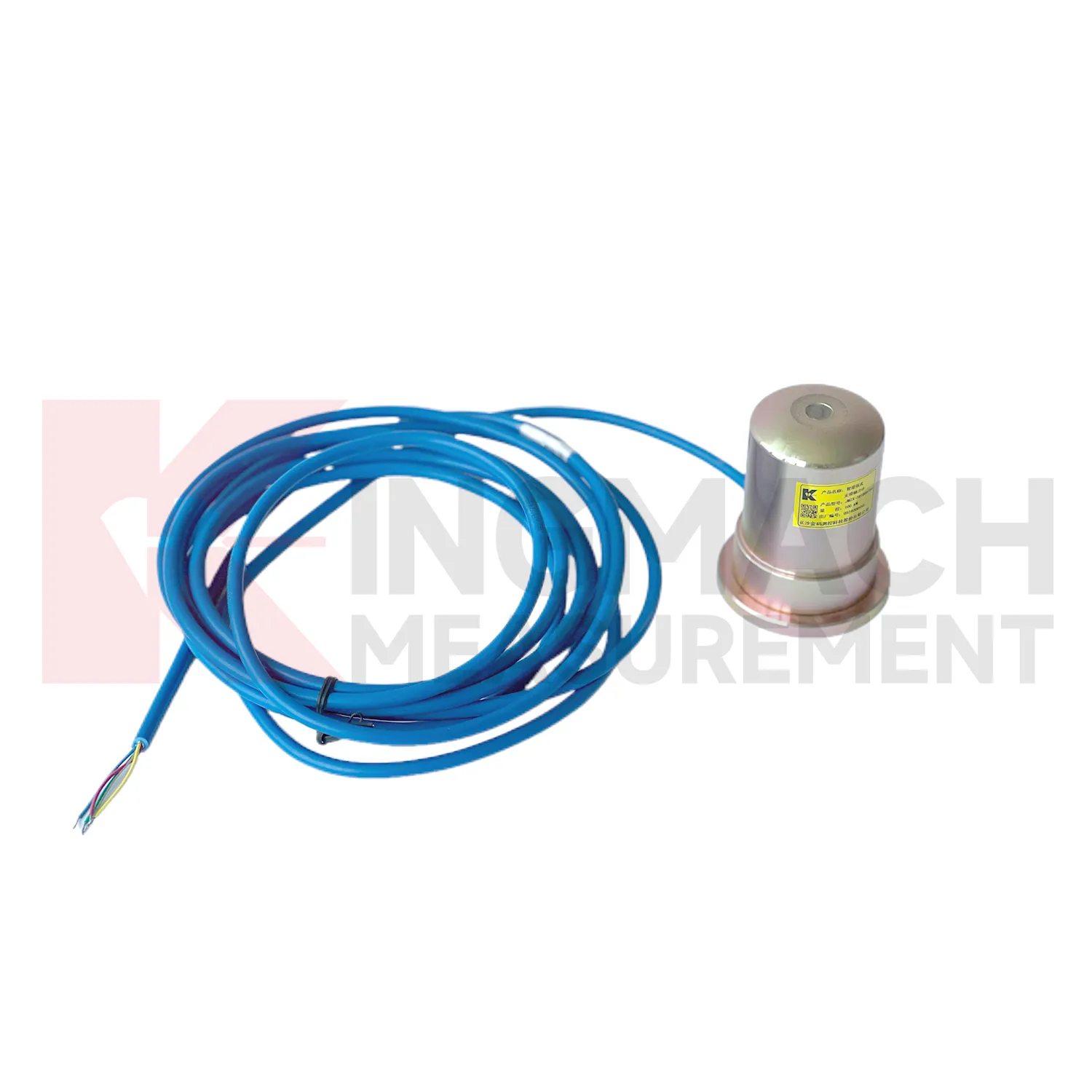
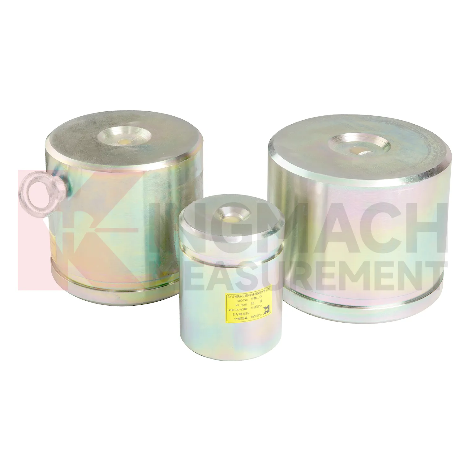
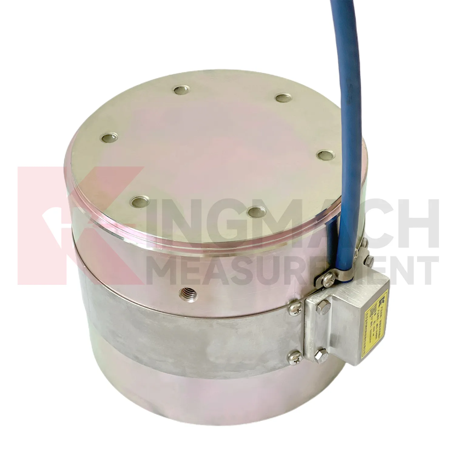
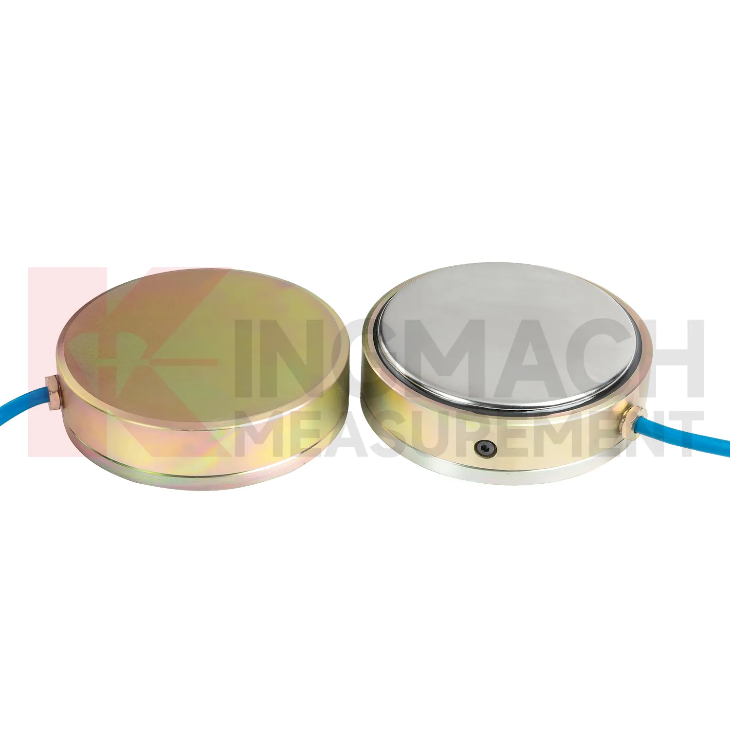
Kingmach Differential Water Level Gauge covers more than one mechanical form, which matters because force does not enter every structure the same way. The solid load cell JMZX-35XXHAT is listed for 1000 kN to 10000 kN with 0.1 kN resolution and 0.5%FS precision. The same product file gives a -30°C to 80°C working temperature range, 20 to 50%F.S. range overload, and 300 to 400%F.S. failure overload. It also stores model, number, calibration coefficient, pressure value, zero parameter, and temperature correction data. These points make it better suited to compression load checks such as pile load testing, bridge pier support measurement, and heavy structural bearing work. The instrument is part of a larger Kingmach monitoring catalog that includes displacement, settlement, tilt, pressure, water level, and acquisition products. For procurement, the practical review should cover capacity margin, bearing surface geometry, calibration documents, expected temperature range, overload exposure, and whether the readings will be taken locally or fed into an automated system. Kingmach also presents the product family alongside project areas such as bridges, dams, tunnels, subways, slopes, buildings, subgrades, wind towers, and foundation pits. That makes the specification less abstract: each model can be matched to a known load path and a known field environment before ordering.
Application of Differential Water Level Gauge
In railways, highways, and transport corridors, Differential Water Level Gauge can monitor bridge support loads, subgrade pressure, retaining structure forces, and temporary works near active traffic. The difficulty is that access windows are short, vibration is frequent, and data gaps can create uncertainty during maintenance review. Kingmach smart load products support digital output, anti-interference transmission, built-in temperature correction, and stored model or calibration information. Solid load cells list 1000 kN to 10000 kN ranges and 0.5%FS precision, while axial force meters cover 200 kN to 3000 kN for support load points. These specifications suit high capacity structural members and staged construction near operating routes. A monitoring plan should record traffic condition, construction activity, temperature, and any maintenance event near the sensor. For owners, the value lies in trend comparison: whether support loads change after traffic opening, whether subgrade pressure rises after heavy rainfall, or whether temporary structures remain within expected force limits before removal. For transport corridors, the inspection schedule should account for possession windows, traffic vibration, and safe access. Remote acquisition may reduce field visits, but periodic visual checks still catch damaged cables, water entry, and loose junction boxes. Access for inspection should also be planned before backfilling, because later hardware checks may be harder than taking the reading itself.
The future of Differential Water Level Gauge
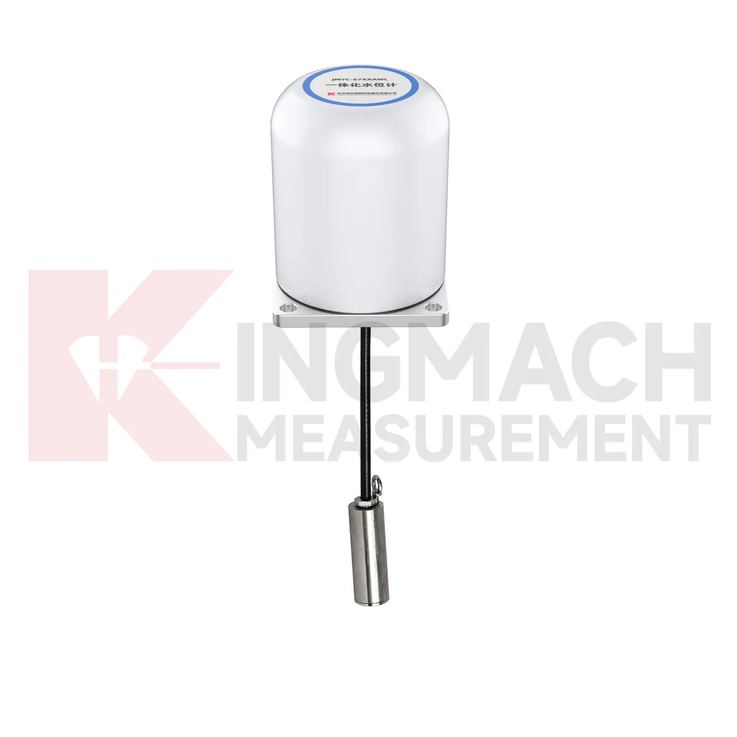
Future Differential Water Level Gauge maintenance will be shaped by long life assets such as dams, bridges, slopes, and transport corridors. Kingmach products that list 50 year design life, waterproof durability, temperature correction, and stored records are already moving in that direction. The next improvement is not just longer service life, but easier proof that the reading remains valid. Owners may require digital calibration files, sensor identity chips, maintenance timestamps, and platform records that survive system upgrades. MEMS sensors, vibrating wire sensors, and smart acquisition units may be used together, with each type assigned to the job it handles best. AI warning models can compare slow force drift with water level, temperature, rainfall, and movement data, but field checks will still matter. A low maintenance design should therefore include sealed connectors, stable cables, lightning protection planning, and clear calibration intervals. Future systems will be judged by how little uncertainty they leave during inspection.
Care & Maintenance of Differential Water Level Gauge
For Differential Water Level Gauge used with manual readouts, care depends on repeatable procedure. Before installation, store the calibration sheet with the instrument and confirm that the readout supports the sensor type. Kingmach product pages mention compatible readouts and comprehensive vibrating wire instruments, which can display force values directly on selected models. During installation, label the cable and channel clearly, record the zero value, and protect the connection point from water and pulling. During each reading round, use the same unit, readout setting, point name, and observation sequence. Note temperature, weather, construction activity, and any visible damage near the sensor. Long term maintenance should include connector cleaning, cable jacket inspection, comparison with nearby points, and periodic calibration planning according to project requirements. If a reading seems wrong, repeat it after checking the cable and readout battery. Many apparent sensor faults come from swapped channels, loose connectors, or missing zero records. Use the same readout settings.
Kingmach Differential Water Level Gauge
Differential Water Level Gauge becomes most useful when the project treats it as part of a measurement chain. The chain starts with model selection and calibration, continues through surface preparation, installation, cable protection, readout setup, and first stable reading, then carries on through reporting and maintenance. Kingmach's range includes products with high capacity force measurement, waterproof construction, smart memory, direct kN display, and compatibility with readouts and automated acquisition systems. Those features only pay off when the field record is disciplined. The sensor should be named consistently, protected from mechanical damage, checked after loading events, and compared with nearby monitoring points. A force value that appears unusual should not be accepted or rejected in isolation. It should be checked against temperature, recent work, cable condition, connector sealing, and the last normal trend before a conclusion is made. That same record can later support warranty review, acceptance files, and maintenance planning. This is especially useful when the same point moves from construction control into long term asset monitoring.
FAQ
Q: When is a solid Differential Water Level Gauge more suitable than a hollow type? A: Solid models are commonly used for compression load, pile load testing, bridge pier support checks, and heavy bearing capacity measurement. Q: What specifications does the Kingmach solid load cell list? A: The JMZX-35XXHAT line lists 1000 kN to 10000 kN ranges, 0.1 kN resolution, 0.5%FS precision, and -30°C to 80°C working temperature. Q: How much overload margin is listed? A: Product information lists 20 to 50%F.S. range overload and 300 to 400%F.S. failure overload. Q: What installation errors affect accuracy? A: Eccentric loading, uneven bearing plates, side load, cable pulling, and missing zero records can all distort results. Q: What records should be kept for acceptance? A: Keep calibration coefficient, model, serial identity, load stages, temperature, zero value, and readout setting.
Reviews
Joshua Clark
We ordered a full monitoring solution including sensors and data loggers. Everything works seamlessly together. Great supplier!
Christopher Martinez
Very satisfied with the readouts & data loggers. User-friendly interface and supports multiple sensor inputs.
Latest Inquiries
To protect the privacy of our buyers, only public service email domains like Gmail, Yahoo, and MSN will be displayed. Additionally, only a limited portion of the inquiry content will be shown.
Ava***@gmail.comAustralia
Hi, I am looking for reliable tiltmeters and accelerometers for structural health monitoring. Please...
Sophia***@gmail.comUnited Kingdom
Good day, we need environmental monitoring sensors including temperature, humidity, and wind sensors...
Related product categories
- calibration of load cell theory
- load cell failure
- load cell technology
- strain gauge load cell wiring
- diagram 4 wire load cell wire connection
- load cell accuracy calculation
- load cell amplifier circuit
- load cell calibration procedure
- load cell excitation voltage
- load cell unit of measurement
- mounting load cells
- strain gauge with load cell